●) Line Following Robot
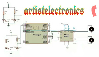
Circuit diagram: Line Follower Robot Circuit Principle: This circuit consists of ATmega8 microcontroller, two IR sensors, motors and motor driver IC. The line follower robot needs mechanical arrangement of the chassis. Assume a two wheel robotic vehicle with a castor wheel. The two IR sensors are mounted on the robot facing towards Earth. When robot is placed on the fixed path, it follows the path by detecting the line. The robot direction of motion depends on the two sensors outputs. When the two sensors are on the line of path, robot moves forward. If the left sensor moves away from the line, robot moves towards right. Similarly, if right sensor moves away from the path, robot moves towards its left. Whenever robot moves away from its path it is detected by the IR sensor. IR sensor consists of IR transmitter and IR receiver on a board. When the vehicle is moving on a black line, IR rays are continuously absorbed by the black surface and there is no reflected ray makin